The Box

It might seem odd that this project is called The Smart Fridge while I’m not using any fridge to make it. Don’t get me wrong. I plan on getting a fridge to put the system into. However, I’m working on the project in New Mexico while I live in Illinois and go to school in California. Rather than try to figure out transportation for a mini fridge between each of these locations, I’m just planning on buying the fridge when I get back to school. This leaves me with a different challenge though. As I add on more modules and sensors, things are starting to get out of control. The easiest way to manage a combination of various small devices is to put them in a box. So that’s what I’ve done. I built a box.

Box1

I personally think the LCD panel and RFID reader look so cute poking though the box. 🙂 The wires leading to the milk scale are connected using male/female header pins so the scale and box can be moved independently from each other. The longer side is connected to the box so that it can be easily swapped for a different length.

FullSizeRender 4Here’s the inside. I’m still using the breadboard and probably will be for a while.

Next up: Taking apart the Egg Minder!

The Hx711

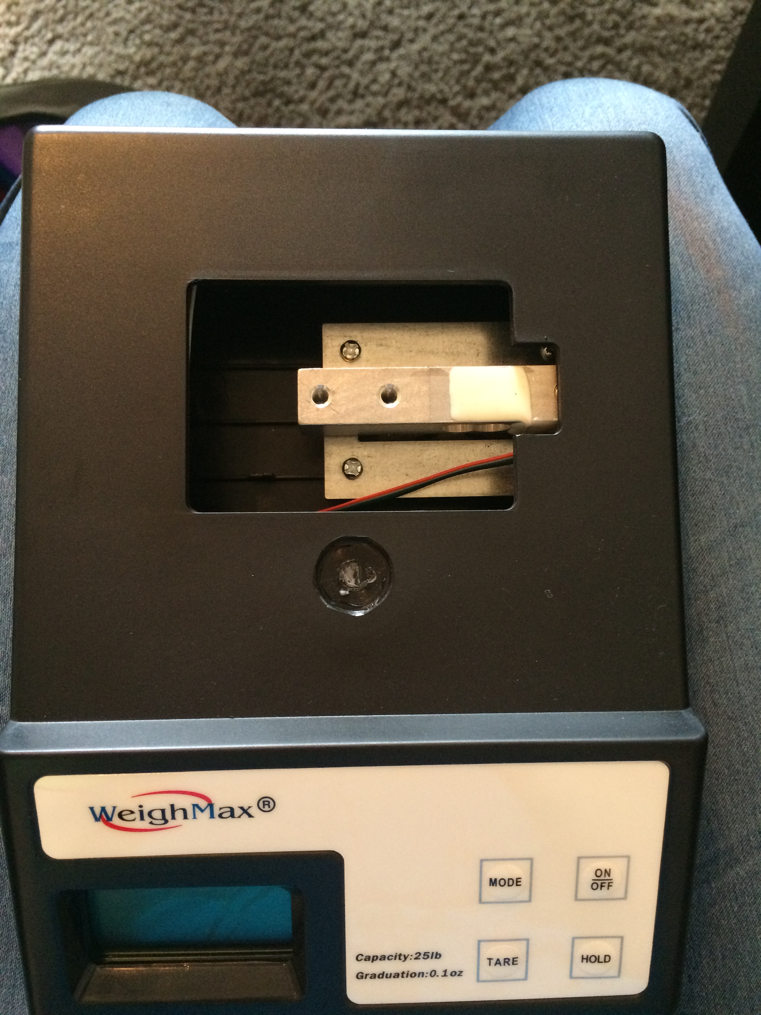
The Hx711 is a 24 bit analog to digital converter for weigh scales. Essentially it takes the four fancy wires from the load cell on the scale I bought and gives out four wires. Of those four wires, one is ground, one is 5v, and two are for information. Beyond supplying wires, the module acts as an amplifier for the signals from the load cell.

Moving on from how it works, I used the blog I mentioned in my previous post to connect the Hx711 to the Arduino and the scale. The library and starter code are both included in the blog. It wasn’t too difficult to get the system running on the starter code.

Unfortunately, the system isn’t exactly consistent. Every so often a random value is read. It also takes a while for the reading to stabilize. In order to provide a more reliable read, I wrote a function that finds the average of five reads and compares it to the average of the next five reads. If the two averages are within 0.1 g of each other, then the reading is accepted as accurate and the two averages are averaged and saved.

While this check provides a decently reliable read, it does take a while to run. And sadly, while it’s running RFID tags can’t be checked in or checked out. To help minimize problems, I’m having the LCD panel display a message until it’s found an accurate reading. This problem is simply a matter of having a slow and not exactly accurate scale. With a better scale system, checking the weight of the milk won’t take five seconds but rather a fraction of a second.

But I seem to be skipping over the fact that IT WORKS! 😀 The code is modified and running. See the text I received!

Text with Milk

IMG_0257

IMG_0259

It’s awesome! It’s really working. Just not on battery yet. I’m running into almost the same problem I had before with getting the system on battery. When I have the LCD panel, the Arduino, and the Hx711 all plugged into the power coming from the 5v regulator, it’s no longer 5v. The voltage is reading around 3.7 – 4.2v directly from the 5v regulator. While this seems enough for the Arduino and the Hx711, it’s not enough for the LCD panel. I’m considering buying a panel from SparkFun that takes 3.3v instead of 5v but I’m not sure if that’s my best solution. I’m still considering. I would really just prefer to solve this problem rather than find a work around. But maybe my work around is my solution. Sigh. I’m just not sure right now.
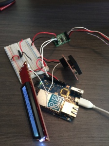
Taking Apart the Scale

Now that the RFID module and the texting are working, it’s time to move onto the next sensor group. The Milk Sensor is going to be coming from a modified mail scale. The mail scale should work perfectly because it can weigh up to 25 lbs with a sensitivity of about an ounce. So the first thing to do is to take apart the scale that I’ll be connecting to the Arduino. Time to see what’s inside.

Mail Scale

The scale bought from Amazon for $16.95

IMG_0221

The first set of screws to remove

IMG_0222

The first peek inside. This would be the bar load cell.

IMG_0230

The next set of screws. These were under the foot pads.

The hidden screw that took me forever to find.

The hidden screw that took me forever to find.

The snaps that worked with the screws to keep the two pieces together.

The snaps that worked with the screws to keep the two pieces together.

The inside of the scale!

The inside of the scale!

From here, I was able to identify the two different power lines. One that comes from the optional plug and the other comes from the 9v battery connector. The wires that I care about are the four wires coming off from the load cell. I had already found a blog that talked me through how to connect this to an Arduino. However, I decided to look into it more to see if there was anything else. And there was! It was actually by the same blog but with a new way to connect a scale to an Arduino. Take a peek.

They now suggest using a Hx711 module which is designed for connecting load cells to Arduinos. Talk about perfect. I quickly found it on Amazon and placed my order. Unfortunately it won’t be in stock until Monday, so I have to wait until Tuesday to receive it. Ah well. Until then, I’ll start looking at the code and figuring out how to put it back together so I can still use it.